Boost converter box for the EcoFlow solar input
Power outages here can be long, and my EcoFlow Delta Max 1600 alone isn’t enough for them. I also have a separate 12 V LiFePO4 battery, so I wanted to connect it to the EcoFlow. The only suitable input is the solar port, and it accepts 11–100 V but at most 10 A. From 12 V that’s only about 120 W, so the voltage has to be raised first.
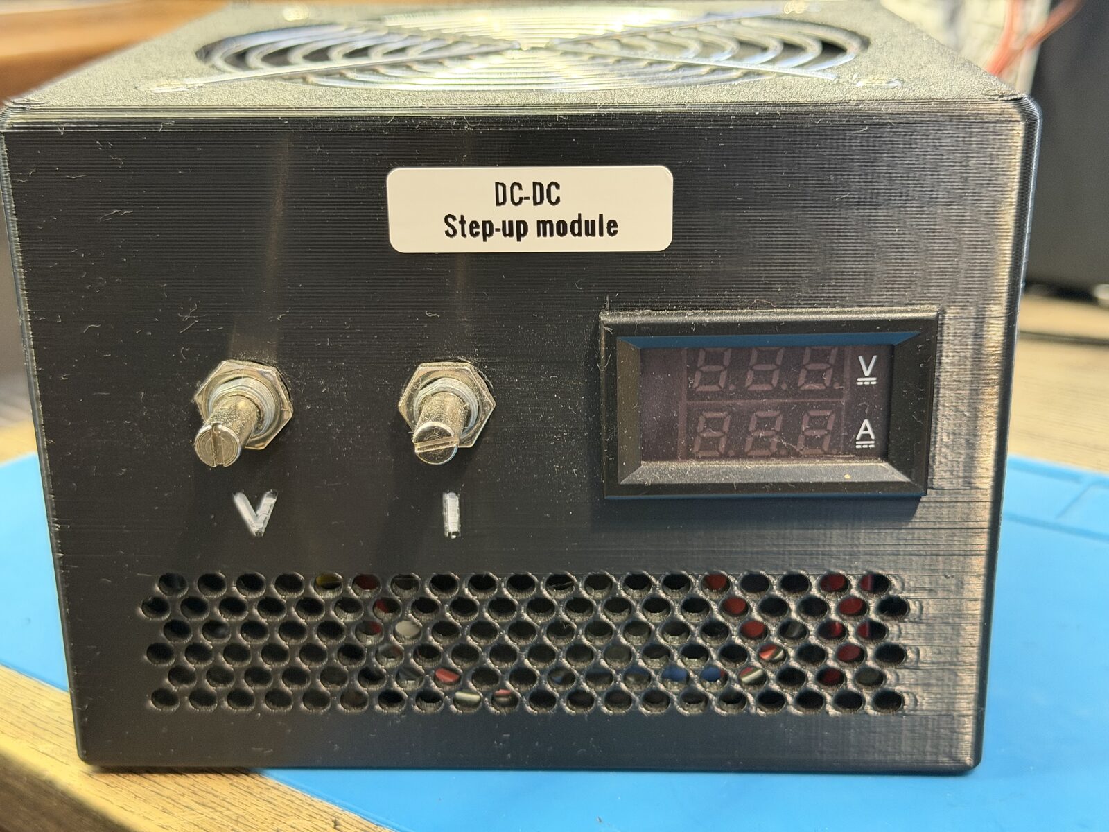
A boost converter module does exactly that, but a bare board with screw terminals and tiny trimmers is not something you want to use every day. So I built it into a box that looks like a PC power supply: knobs for voltage and current, a meter, a breaker and XT60 ports. The box doesn’t care what is connected to it, so it works with any 10–60 V DC source.
How it works
    flowchart LR
  SRC["DC source<br/>10–60 V"] --> IN["XT60 IN"] --> BOOST["Boost module"]
  BOOST --> METER["Meter<br/>V / A"] --> CB["Breaker<br/>20 A"] --> OUT["XT60 OUT"]
  OUT --> CABLE["XT60 → XT60i cable"] --> EF["EcoFlow<br/>solar input"]
  BOOST -- fan port --> FAN["120 mm fan"]
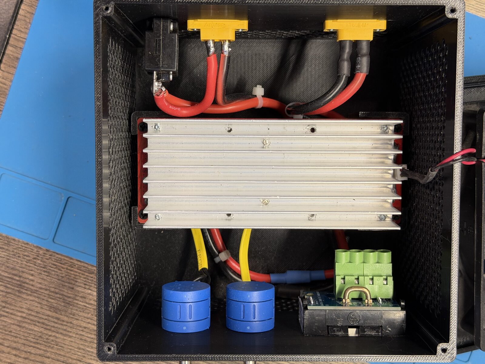
- Boost module is an 1800 W CC/CV boost converter: 10–60 V in, 12–90 V out. The V knob sets the output voltage, the I knob limits the output current.
- Meter shows the output voltage and current.
- Breaker is a 20 A resettable circuit breaker on the output.
- Fan is a 120 mm PC fan on the module’s own fan port. The module’s temperature controller turns it on only when the board gets hot (about 60 °C), so most of the time the box is silent.
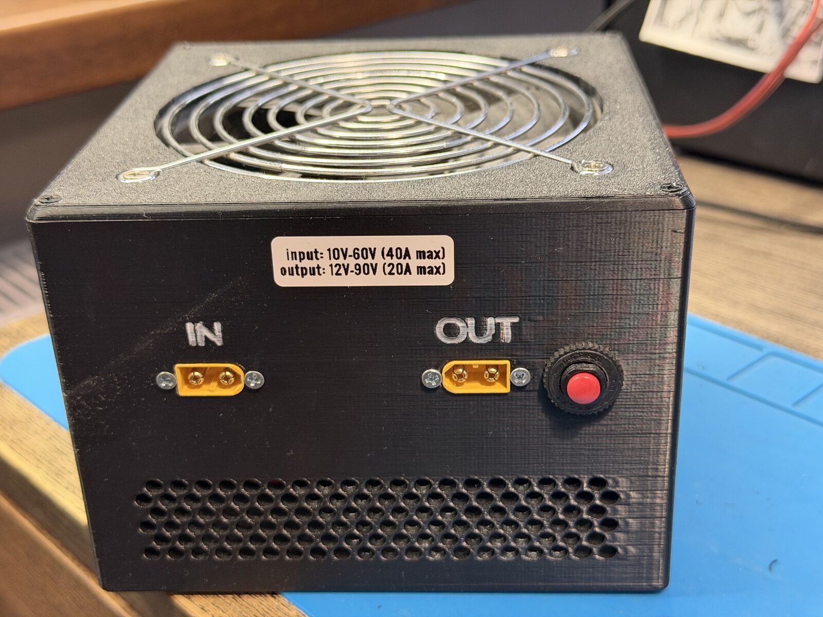
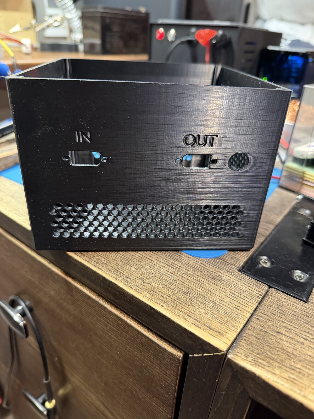
- XT60 IN / OUT on the back. The label shows the limits, so I don’t have to remember them.
Settings
I usually set it to about 20 V with the current limit at 13 A, which is about 260 W. I choose the power to cover what the EcoFlow is currently powering. Then the load runs from the external source and the EcoFlow battery stays where it is: no energy lost on charging it just to discharge it again. With more power the EcoFlow turns on its fans, and they are very loud.
The 13 A cable
The EcoFlow solar input is an XT60i connector. The small middle pin tells the EcoFlow what is connected: positive means a car socket, and the current is limited; negative means solar. With a cable that has the middle pin connected to negative, my Delta Max takes 13 A instead of 10.
I made such a cable: a regular XT60 on the box side and an XT60i on the EcoFlow side, with a wire from the middle pin to the negative contact.
Parts
| Part | Details |
|---|---|
| Boost | 1800 W 40 A DC-DC boost converter, 10–60 V → 12–90 V |
| V knob | 3590S-2-104L, 100 kΩ 10-turn potentiometer, replaces the CV trimmer |
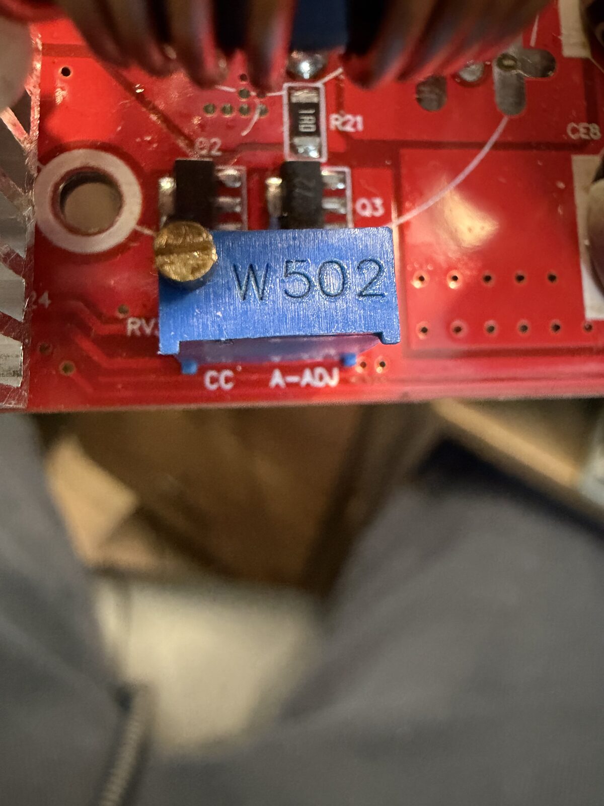
| I knob | 3590S-2-502L, 5 kΩ 10-turn potentiometer, replaces the CC trimmer |
| Meter | DC 7–100 V 20 A voltmeter/ammeter |
| Breaker | 20 A resettable circuit breaker |
| Fan | 120 mm PC fan |
| Connectors | 2× XT60 |
| Enclosure | My own 3D-printed case |
Build
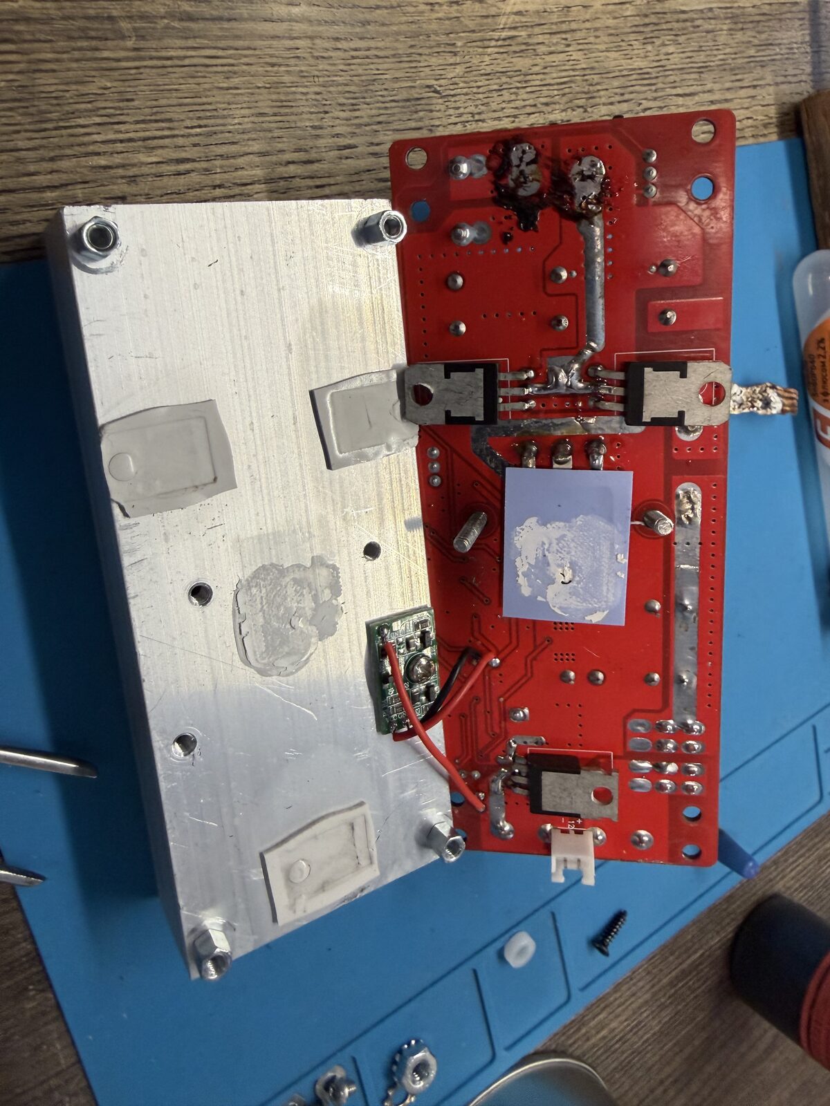
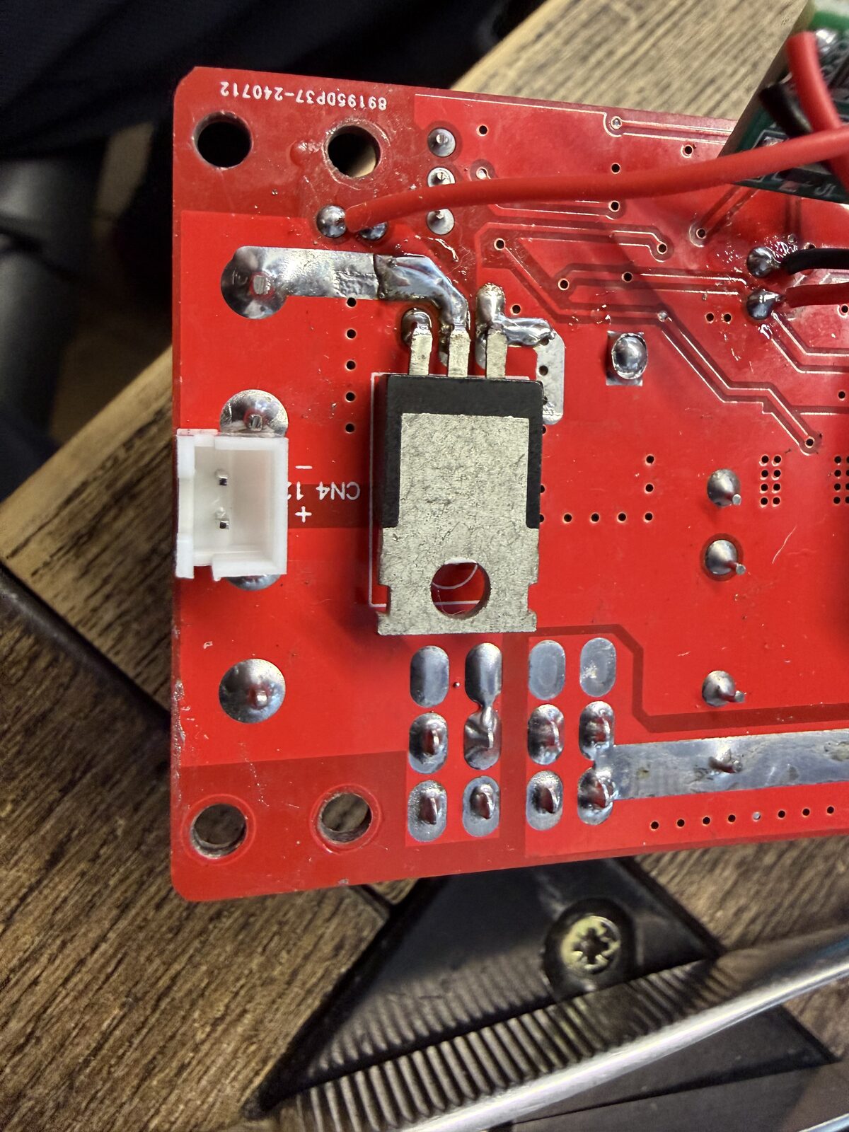
The module itself is stock, including the heatsink, the onboard fuses and the fan temperature controller. I only took it apart to replace the two trimmers with 10-turn potentiometers on wires, which go to the front panel.
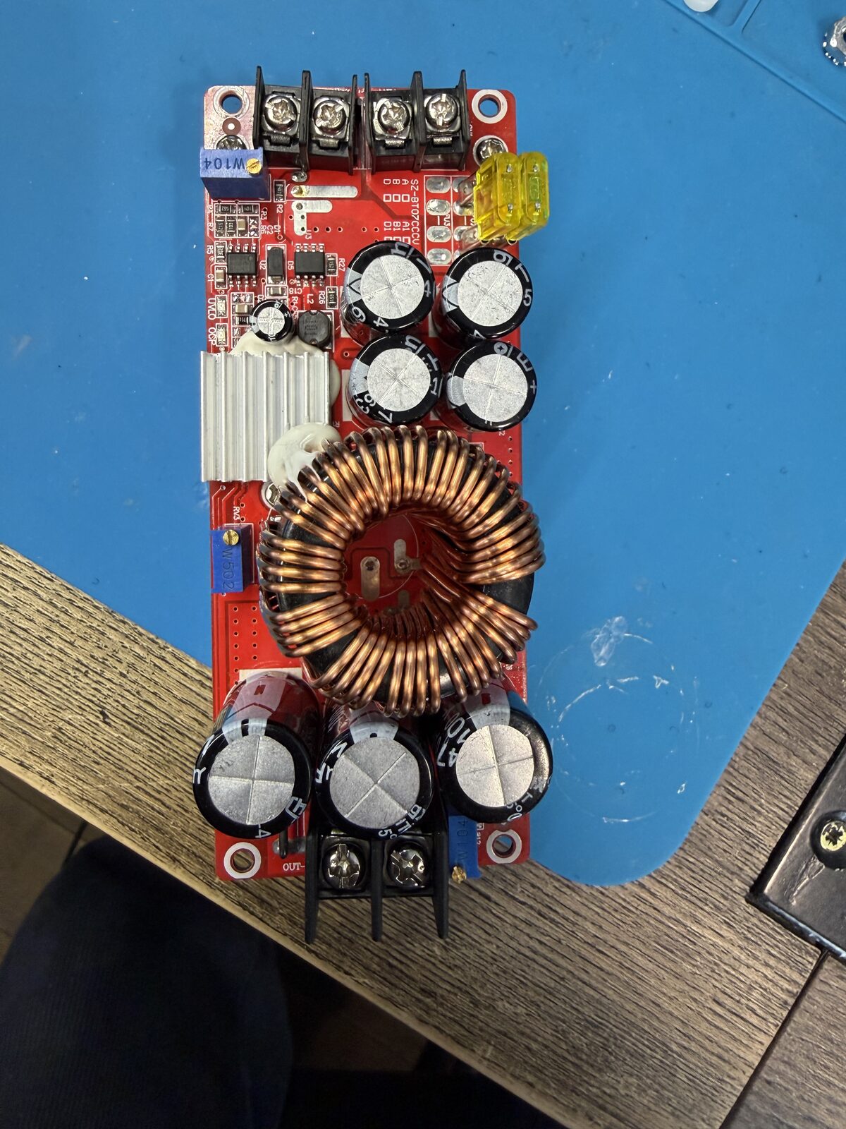
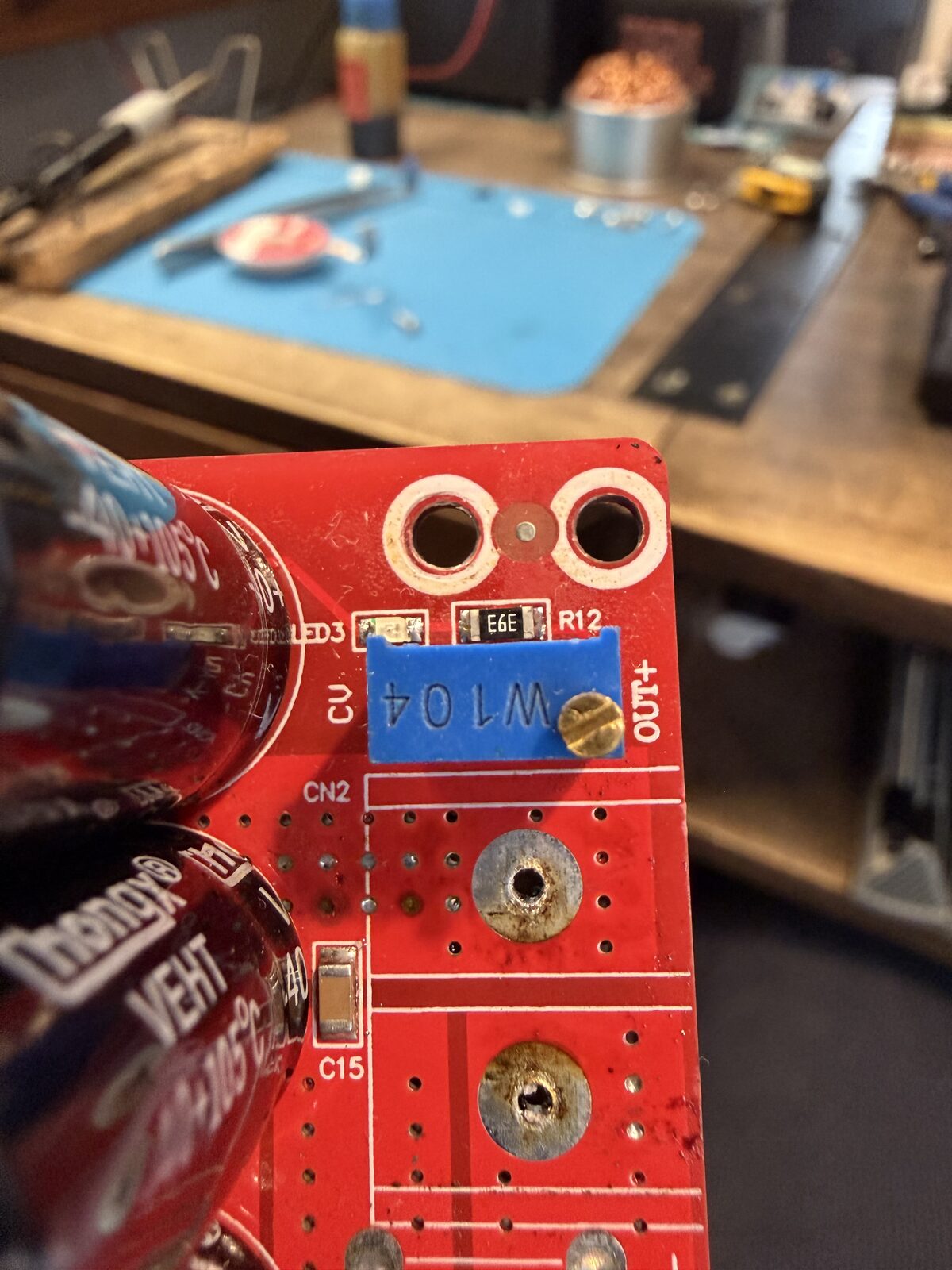
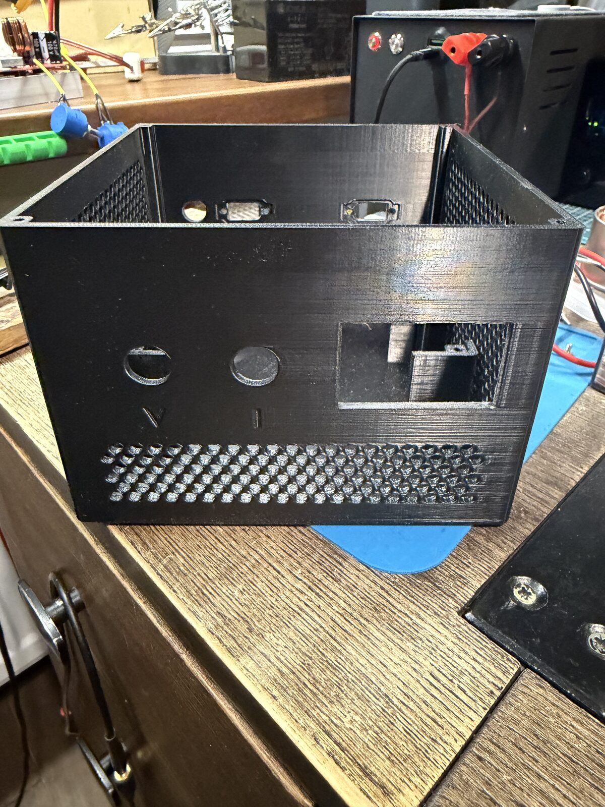
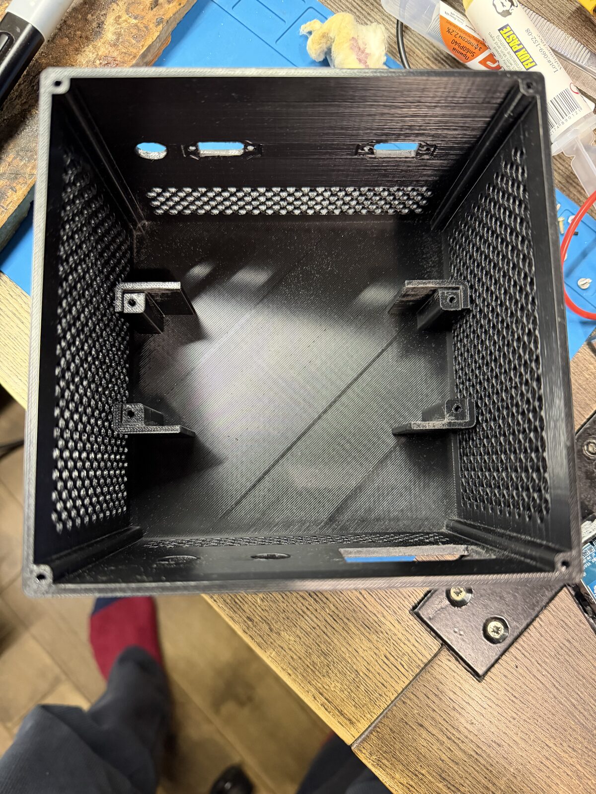
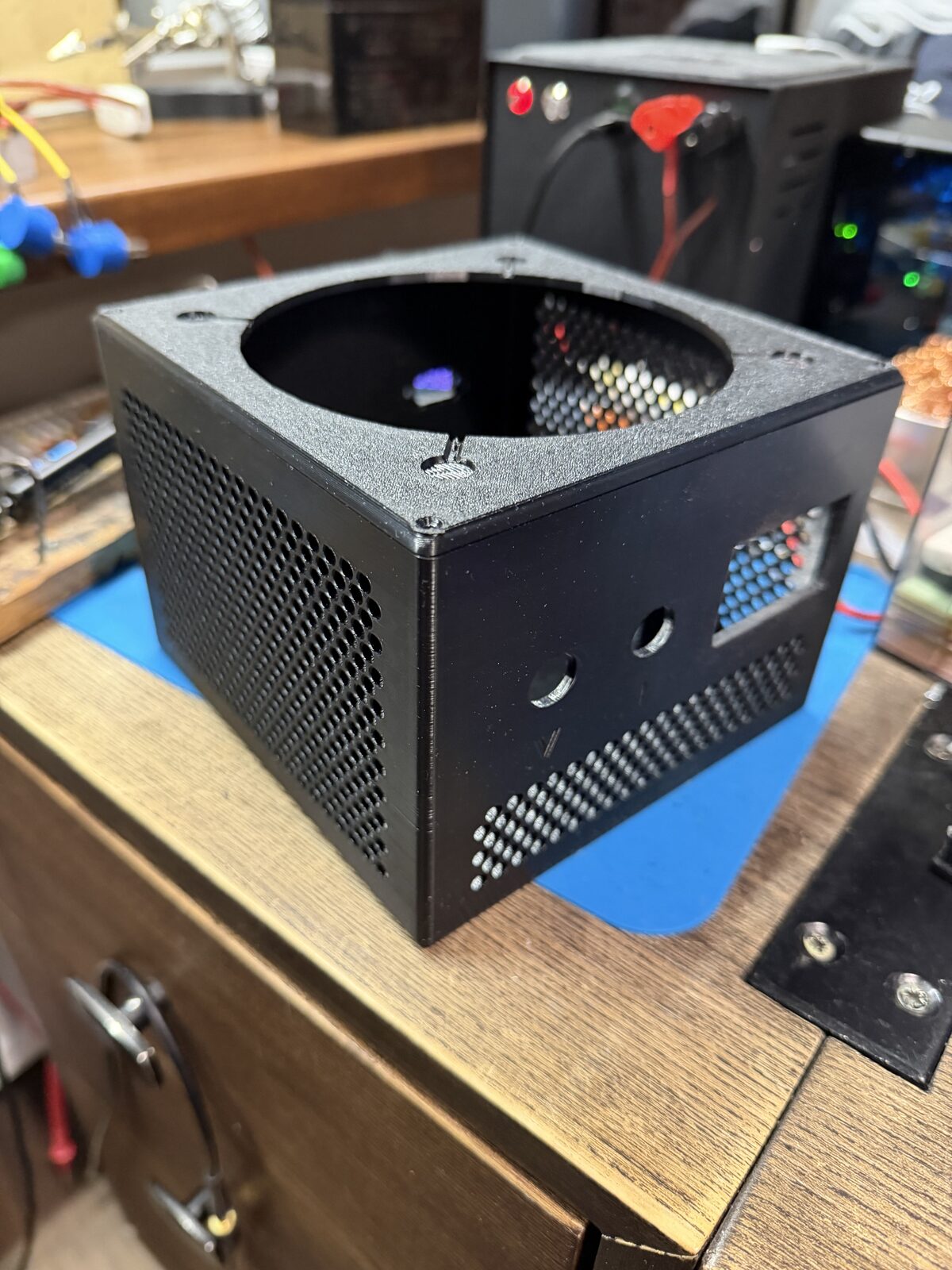
The case is inspired by a PC power supply: the shape, perforated sides and a 120 mm fan with a grille on top.
Result
The EcoFlow can now use my 12 V battery, or any other 10–60 V source, through its solar input. Once the knobs are set, the box is just two XT60 cables and a meter. During long outages the external battery powers the load through the EcoFlow, and the EcoFlow stays quiet and keeps its own charge for later.